

Royal Canadian Mounted Police
www.rcmp.gc.ca
Common menu bar links
G13-02 Secure Demising Wall (SDW)
Physical Security Guide
Lead Agency Publication G13-02
Issued: July 2013
Table of Contents
- Definitions
- Abbreviations
- References
- Referenced Commercial Standards
- PART 1 (For use by the Department or Agency)
- PART 2 (SDW Construction Specifications)
- Figures:
- Figure 1: Wall Construction
- Figure 2: Welding Steel Mesh
- Figure 3: Welding Sheet Steel
- Figure 4: Riveting Sheet or Mesh
- Figure 5: Example of Mesh Interlay Seam, Riveted
- Figure 6: Critical Attack Area Wall Reinforcement
- Figure 7: Frame Reinforcement at Door
- Figure 8: Ceiling Mount Duct Pass-Through
- Figure 9: Surface Mount Duct Pass-Through
Definitions
Authority Having Jurisdiction - Normally the local city, municipality or county building inspector. For Canadian Forces Bases the Authority Having Jurisdiction will be the Canadian Forces Fire Marshall.
Attack Side - The side of the door or wall that is exposed to the adversary.
Base-line Threat - Threats common to government departments in Canada, under normal security conditions, as defined in the Operational Security Standard on Physical Security.
Designer - A qualified person (architect, engineer, technologist or other) tasked to develop the specific project design (drawings and specifications) based on the client-generated Statement of Requirements (SOR) and conforming to the overall project and code requirements.
Secure Demising Wall - A force-resistant wall constructed according to RCMP Guide G13-02.
Secure Working Room - A specially designed room, suite of rooms or spaces used for the processing and open shelf storage of classified information.
Statement of Requirements - The client-generated list of project-specific requirements (especially selection of optional alternatives) for the SDW. The SOR should be developed from the advisory information in Part I of this Guide, along with specialist advice as required.
Open Shelf Storage - Storage other than in approved security containers and safes. Open shelf storage includes storage where records are kept in containers or commercial fire and/or water resistant containers.
Zones - Defined in Reference B.
Abbreviations
- dB - Decibel
- Ga - Sheet metal gauge indicating the standard thickness of the sheet metal
- SR - Secure Room (+ suffix indicating Secure Room “Type” as per earlier versions of G1-029)
- SDW - Secure Demising Wall
- SSR - Secure Storage Room
- SWR - Secure Working Room
- SOR - Statement of Requirements
- STC - Sound Transmission Classification
- TRA - Threat and Risk Assessment
- ID - Inside diameter
- OD - Outside diameter
- oc - On centre
- Ø - Bar diameter
References
Referenced Commercial Standards
The following standards are available for purchase from their respective standards associations, or from standards vendors such as IHS Standards, the ANSI Store or Techstreet
ASTM A627-03: Standard Test Methods for Tool-Resisting Steel Bars, Flats, and Shapes for Detention and Correctional facilities
American Society for Testing and Materials
ASTM F1267-07: Standard Specification for Metal Expanded Steel
American Society for Testing and Materials
CAN/CGSB-1.60: Interior Alkyd Gloss Enamel Paint
Canadian General Standards Board
EMMA 557-99: Standard for Expanded Metal, Introduction, Product Selection Considerations, Terminology, Manufacturing Process, Manufacturing Tolerances and Applications.
Expanded Metal Manufacturers Association
SSMA: Product Specifications
Steel Stud Manufacturers Association
PART 1 (For use by the Department or Agency)
How to Use This Guide
This Guide is intended to assist qualified security practitioners and departmental physical security staff to develop a Statement of Requirements (SOR) for the construction of a Secure Demising Wall (SDW).
Qualified architects or designers should be engaged to turn the SOR into detailed drawings and specifications – incorporating all client-specified features and components and ensuring that the design conforms to overall project requirements and all applicable codes and facility “fit-up” standards.
The rationale for any component or feature (as well as the purpose of a space or nature of the asset) should only be divulged to architects, designers or contractors on a need-to-know basis. They may require a security clearance to receive this information.
Segregation of details and distribution on a need-to-know basis will often be sufficient. The architect or designer should be provided with formal guidance / direction on the preparation of drawings for tender or sub-trades to ensure that sensitive information is not inappropriately divulged. For example, the purpose or name of the room should not appear on widely disseminated drawings, specifications or other contract documents. A generic or numeric name should be used. Sub-trades should receive only enough information to perform their work (eg: partial building drawings and system schematics which do not identify adjacent activities or security-related system details). Security requirements should be incorporated into contract documents where feasible to ensure enforceability.
General
For many years, various departments have been using portions of the construction specifications from the G1-029 Secure Room Guide 1 to construct walls around departmental space (e.g., in office towers), working spaces, operations rooms, High Security Zones, etc.
This guide was developed specifically for the construction of a secure demising wall and to help avoid inappropriate use of the Secure Storage Room Guide (see note 1). Having a name, abbreviation, definition and guide number specifically for a Secure Demising Wall (SDW) also makes it easier to reference source material without confusion.
The wall design in this Guide is a tested and recommended light weight construction to adequately mitigate the design-basis threat against typical government offices in standard urban settings. It provides moderate resistance to force attacks (including those using portable cutting tools) and very good detection of such attacks (when approved vibration detection equipment is installed as recommended). This wall construction is not appropriate where a TRA has identified a need to provide an assured resistance to entry by sustained force attacks. UL-rated vaults or custom-designed barriers should be considered for such situations.
Note 1 - The Secure Room Guide G1-029 was updated in 2013 and renamed the G13-01 Secure Storage Room Guide to better reflect its intended application.
Application
Secure Demising Walls (SDW) are suitable for physically separating an Operations Zone from a Public/Reception Zone, or (when recommended in a TRA) to separate a Security Zone from an Operations zone or compartmentalize within a particular zone.
Secure Demising Walls facilitate detection and provide a delay to permit interception by an appropriate response within a reasonable time. It should be stressed that a rapid and appropriate response is key to the effectiveness of any delay and detection/ alarm security system.
Sound Reduction
An SDW was not designed for speech security and should never be the separation between a Sensitive Discussion Area (SDA) and a Public Zone. An SDA should be a room located in a Security Zone (whose perimeter walls may be a SDW).
However, sound reduction should normally be included to reduce nuisance noise and minimize the opportunistic overhearing of conversations which - although not classified - may still be considered sensitive.
Construction resulting in an STC of 54-55 dB is generally adequate for SDW applications.
The following assembly will provide an STC rating of approximately 54-55:
- Two layers of 16 mm fire-rated gypsum board
- One layer of sheet or expanded mesh steel
- Steel studs spaced 300 mm oc
- 150 mm thick glass fiber batts between studs
- Resilient metal channels spaced 400 mm apart
- One layer of 16 mm fire-rated gypsum board
This rating is for the wall assembly without pass-throughs or gaps. Acoustic caulking must be applied between the gypsum board and all adjacent surfaces to prevent sound leakage through spaces and gaps.
Doors installed with typical commercial seals (or acoustic seals improperly installed or adjusted) will generally not provide better than 35 dB sound reduction even when the doors are acoustically rated. As the intent of a SDW is not acoustic isolation (and many applications will involve commercial architectural doors and windows for visibility, public impact and accessibility), this should not be an issue. Vestibules can be helpful.
Fire Protection
Double panel or Type X drywall sheets may be installed as required to meet fire code requirements. Friction fit (batt) insulation must be used. Sprayed-on insulation must not be used as it may interfere with the transmission of vibrations along the sheet steel.
Slab-to-Slab
Secure Demising Walls should be slab-to-slab, i.e., from the finished structural floor to the underside of the structural roof /ceiling. Where roofs or floors are of wood or steel frame construction they should be steel reinforced the same as the walls. Where this is not feasible, other mitigation measures will be required. For guidance regarding the construction of a secure ceiling or floor, please contact the RCMP.
Secure Demising Wall Built Adjacent to Another Wall
When building Secure Demising Walls adjacent to non-departmental walls (e.g. leased spaces where modifications to the existing walls are not permitted under the occupancy instrument), the protective material will need to be installed on the secure (inside) side of the wall and all electrical and alarm wiring should be in surface-mounted conduit.
Ducts and Other Service Penetrations
Minimize ducts and service pass-throughs in Secure Demising Walls where possible. Do not locate pass-throughs in the Critical Attack Area around doors. Where pass-throughs are required, openings should be framed with studs to within 1” (25mm) of the pipe/conduit and the pipe or conduit secured to the stud framing at minimum two places. The wall protection material should be extended to within ¾” (20 mm) of the edge of the opening. Extend gypsum wall board to the edge of the pipe or conduit. Caulk all gaps with fire rated sealant. Recommended standard: ASTM E 814 (UL 1479) and CAN/ULC S115 or as required by the AHJ.
Where necessary to accommodate pipe or conduit movement or expansion, pipes and conduits may be enclosed in a close-fitting sheet metal sleeve and the sleeve mechanically fastened to the stud framing at minimum two places. Clearance between the sleeve and the pipe or conduit should be kept to a minimum and not exceed ¼”.
Steel bars (see Figures 8 & 9) should be installed in ducts in Public or Reception Zones to delay access of a person through a duct. They may be omitted if it is determined in a TRA that it is not a viable threat due to other security controls. Note that Man Bars do not prevent possible destruction, modification or interruption to assets within by introduction of water or other material through a duct. If a TRA identifies such threats, all ducts and openings may require additional mitigation measures (e.g.: filters or dampers).
Vibration Detector
While the sheet steel on the walls provides moderate force resistance, one of the main reasons for the steel sheets on the wall is to transmit vibrations from force attacks to vibration sensors. A volumetric intrusion detection sensor (e.g. motion sensor) located in the room or space is also recommended, but will not detect the adversary until he/she has already defeated the SDW, doors, windows or components and gained entry. As the purpose of intrusion detection is to generate a response in time to intercept the adversary, detection only upon entry reduces the available response time.
The RCMP has tested and approved a vibration detector for use with the SDW, which is listed in the G1-001 Security Equipment Guide (SEG). To ensure detection as per approval testing, the detectors must be installed directly on the steel at a stud/ joist using the base plates provided by the manufacturer.
Sensors should be spaced following the manufacturer’s recommended spacing with at least one sensor per wall segment to ensure good attack detection. A sensor should also be installed on the door (in addition to a magnetic contact switch to detect if a door is opened surreptitiously) to ensure good detection of cutting or pounding attacks against the door/lock.
Doors, Locks and Windows
Doors and windows installed in a SDW should provide moderate resistance to force attacks. Options may include: burglar-resistant glazing, security films, exterior security grilles or screens (typically of expanded metal mesh on steel frames) or lockable steel rolling window shutters. Due to the wide diversity of products and applications, the RCMP has not developed standard guidance for these items.
Statement of Requirements
Where the department (client) is not also the Designer, a Statement of Requirements (SOR) should be developed to tell the Designer exactly what is required and to identify selected construction options from those presented in the General Specifications in Part II.
The SOR and all documentation leading to the selection of room or wall specifics should be considered sensitive and treated accordingly.
Do not tell the designer why a selection has been made unless the designer has a need to know.
PART 2 - SDW Construction Specifications
Note: The specifications in this Part should be modified as required and incorporated into the Project Contract Documents by the Designer in accordance with client requirements (ideally outlined in a detailed SDW Statement of Requirements) and overall project and code requirements.
Wall Framing (Figure 1)
Extend wall partition framing slab to slab.
Top and Bottom Tracks:
SSMA standard: 1- 5/8” x 6”, 18ga (600T162-43); OR
2” x 6”, 18ga (600T200-43) (Preferred Option)
Secure top and bottom steel stud track to both slabs at 300mm oc using any expanding (preferably double expanding) mechanical fastener. Non-expanding (e.g. “Tapcon”) screws are not acceptable.
Studs:
SSMA standard: 1- 5/8” x 6”, 18ga (600S162-43: 33ksi); OR
2” x 6”, 18ga (600S200-43: 33ksi) (Preferred Option)
Space studs at 300 mm oc and secure to the top and bottom tracks with welds or rivets (not screws).
Install double (jamb) studs at the door frame opening. Install the door frame as per HMMA 840-07, part 3 A, B, C, D and E (except that screws shall be replaced with steel rivets).
Install anti-spread bracing approximately 48” from the bottom of the wall between the door frame double stud and the adjacent stud on both sides of the frame.
Construct wall corners with double studs.
Notes: Leaving a small gap and using drywall sheets to brace frame sections during wall erections is permitted provided steel sheets on the attack side are continuous over all gaps.
Figure 1: Wall Construction
Wall Protection Material (Figures 2 to 5)
Wall protection material may be one of two options:
Flattened Metal Mesh: To EMMA 557-99. Style ¾-9F: nominal strand thickness of 0.120” (0.108” to 0.132”). Diamond opening of 0.563” x 1.688”.
OR
Sheet Steel: 16 Ga, A1008 / A1008M (cold rolled) or A1011/ A1011M (hot rolled) or equivalent.
Mount on the outside (attack side) of the room. Support all edges by anti-spread bracing, studs or corners. Align the sheet edges at every vertical and horizontal seam on the centre line of the steel stud or anti-spread bracing and secure all sheets with welds or rivets.
Note: Screws (including “security screws”) are NOT acceptable for permanently attaching the protection material (steel or steel mesh). Screws may be used to “tack’ the sheets in place pending riveting or welding. Temporary screws do not need to be removed.
Welding (Alternate Method)
Steel mesh (Figure 2): 3mm fillet weld along the strand at 200mm oc
Figure 2: Welding Steel Mesh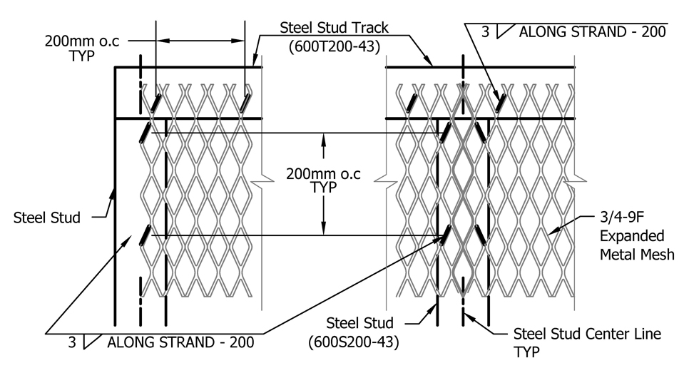
Steel Sheet (Figure 3): 1.5mm fillet weld 15mm long at 200mm oc OR 8mm plug weld at 200mm oc
Figure 3: Welding Sheet Steel
Rivets (Preferred Method) (Figure 4):
Steel sheet: 3/16" steel rivets at 200mm o.c.
Steel mesh: 3/16" steel rivets and “fender” washer (1 ½ " OD, 3/16’’ ID) at 200mm o.c.
Suggested material:
Rivets: 3/16” steel pop rivet: Speaneur part #301-440
Washers: 1 ½ " OD, 3/16’’ ID “fender” washer: Fastenal part #1133204
Figure 4: Riveting Sheet or Mesh
Steelmesh Interlay Seam (Figure 5):
Figure 5: Example of Mesh Interlay Seam, Riveted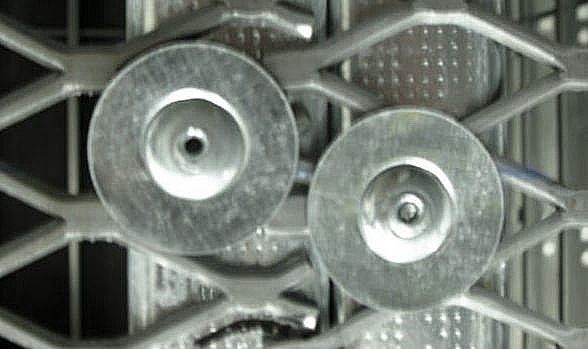
Critical Attack Area (Figure 6)
Install 16 ga sheet steel on the inside of the room and extend 1200 mm from the edge of the door frame. Attach as per rivet or welding requirements for selected method.
Note: Perforations for services, conduits or ducts are not permitted in the Critical Attack Area.
Figure 6: Critical Attack Area Wall Reinforcement
Wall Finishing Details
Attach drywall on both sides using standard drywall screws.
Apply fire-rated sealant continuously on both sides of the top and bottom of partition.
ASTM E814 (UL1479), ASTM E1966 (UL 2079) or CAN/ ULC S115 test standards with a fire/ smoke rating acceptable to the Authority Having Jurisdiction (AHJ).
Paint exterior surface of wall slab-to-slab. Paint must be uniform and without blemishes. Joints must not be visible. Recommended: 1 coat primer/sealer and 1 coat alkyd, gloss enamel conforming to CAN/CGSB‑1.60.
Frame reinforcement at Door (where appropriate) (Figure 7):
Secure a 6.4 mm x 25 mm x 610 mm steel plate inside the frame and align centre with the lock bolt.
Figure 7: Frame Reinforcement at Door
Ventilation Duct Pass-throughs
Note: Where superior resistance to cutting is required, steel bars can be specified as tool‑resistant steel (grade 1 or 2) per ASTM A627.
Ceiling mount: (Figure 8)
- The duct sleeve must be at least the same thickness as the duct passing through.
- The overall dimension of the sleeve must be slightly greater than the duct.
- Construct frames of 1- 3/8” x 1- 3/8” x 1/8” angle steel welded around duct sleeve (ceiling mount brackets are recommended).
- Space 3/8” Ø steel bars at 6” oc and weld to the frame.
- Secure the duct sleeve to the structural ceiling with mechanical fasteners.
- Cut protection material ¾” max from the edge of the duct opening (3 sides)
- Apply fire-rated caulking between duct sleeve and finished wall.
Figure 8: Ceiling Mount Duct Pass-Through
Surface Mount: (Figure 9)
- The duct sleeve must be at least the same thickness as the duct passing through.
- The overall dimension of the sleeve must be slightly greater than the duct.
- Construct frame on each side of the wall of 1- 3/8” x 1- 3/8” x 1/8” angle steel welded around duct sleeve.
- Space 3/8” dia man bars at 6” oc and weld to the frame.
- Secure duct sleeve with ¼” dia bolts and hex nuts (inside the room) at 8” oc around the outside duct sleeve. The bolt head shall be on the attack side and be welded in at least three places to the angle frame.
- Framing around duct sleeve is required.
- Apply fire-rated caulking between duct sleeve and finished wall.
Figure 9: Surface Mount Duct Pass-Through
Advice and Guidance
Royal Canadian Mounted Police
Departmental Security Branch
Physical Security Section
1426 St. Joseph Boulevard
Ottawa, Ontario K1A 0R2
Email: RCMP.LSA-GRC.POSM@rcmp-grc.gc.ca